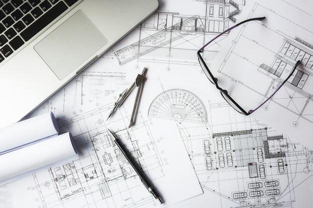
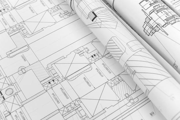
Welcome to our blog post where we aim to clear up any confusion surrounding the terms “engineering graphics” and “engineering drawing”. If you are an engineering student or professional, you may have come across these terms and wondered if they refer to the same thing or if there are any differences between them.
In this article, we will explore these two concepts and break them down for you, providing a clear understanding of what they entail. We will also touch upon related topics such as orthographic views, types of projection, regular views, hidden lines, and reading 1st and 3rd angle drawings. So let’s dive in and unravel the mysteries of engineering graphics and engineering drawing!

Is Engineering Graphics the Same as Engineering Drawing?
When it comes to engineering, there are many terms that may seem interchangeable, leading to confusion among newcomers. One common question that arises is whether engineering graphics and engineering drawing refer to the same thing. Well, let’s dive into this topic and shed some light on the matter!
Understanding Engineering Graphics
Engineering graphics is an essential aspect of the engineering field, encompassing various techniques and tools used to communicate design ideas and technical information. It involves the creation and interpretation of visual representations, such as charts, graphs, and diagrams, to convey complex engineering concepts.
The Art of Engineering Drawing
On the other hand, engineering drawing, also known as technical drawing, focuses specifically on the representation of physical objects or structures using standardized graphical symbols and conventions. It provides precise details about dimensions, materials, and other specifications necessary for the manufacturing or construction of a product.
So, What’s the Difference
While engineering graphics and engineering drawing share a close relationship, there is indeed a distinction between the two. Engineering graphics provides a broader scope, incorporating various visualization techniques beyond just technical drawings. It encompasses computer-aided design (CAD), three-dimensional modeling, and other visual representation methods.
In contrast, engineering drawing is a specific subset within the realm of engineering graphics. It involves creating accurate and detailed two-dimensional or three-dimensional depictions of objects or structures, ensuring adherence to industry standards and specifications.
The Allure of Engineering Graphics and Drawing
Both engineering graphics and engineering drawing play vital roles in the engineering world, complementing each other in the pursuit of effective design communication and technical documentation. From the early stages of conceptualization to the final manufacturing processes, these disciplines enable engineers to convey their ideas, collaborate with others, and ensure accurate implementation.
Whether you’re a seasoned engineer or just starting on your engineering journey, having proficiency in both engineering graphics and engineering drawing can greatly enhance your ability to communicate and visualize designs effectively.
Wrap-Up
In conclusion, engineering graphics and engineering drawing are closely related yet distinct fields within the realm of engineering. While engineering drawing focuses specifically on technical visual representations, engineering graphics encompasses a broader range of visualization techniques. By appreciating the nuances between the two, engineers can leverage these skills to convey their ideas accurately and efficiently.
So, the next time someone asks if engineering graphics is the same as engineering drawing, you can confidently enlighten them with your newfound knowledge! Remember, mastering both disciplines is vital for success in the fascinating world of engineering.
Now that we’ve clarified the difference between engineering graphics and engineering drawing, let’s delve deeper into the exciting world of technical drawings and explore some essential concepts and techniques.

FAQ: Is Engineering Graphics the Same as Engineering Drawing?
In this FAQ-style subsection, we’ll tackle some commonly asked questions about engineering graphics and engineering drawing, providing clear and humorous answers to help you grasp the concepts and their differences. So, grab a cup of coffee and let’s dive right in!
What are the 4 Orthographic Views
Orthographic views are a way of representing a three-dimensional object on a two-dimensional plane. In engineering graphics, the four primary orthographic views are:
- Front View: This view shows the object as if you were looking at it head-on, usually from the reference point.
- Top View: Imagine placing the object on a glass table and looking at it from above. That’s the top view!
- Right Side View: Picture the object beside a transparent wall, where you can see its right side. That’s the right side view.
- Bottom View: The bottom view is what you would see if you magically flipped the object upside down and looked at it from above.
What are the Two Main Types of Projection
The two main types of projection are orthographic projection and perspective projection.
-
Orthographic Projection: This type of projection is commonly used in engineering graphics and drawing. It represents an object using parallel lines of sight and creates accurate views of an object’s features.
-
Perspective Projection: Perspective projection aims to simulate how the human eye perceives objects in three dimensions. It provides a more realistic view with foreshortening and vanishing points, which can be useful in architectural and artistic work.
What are the Three Regular Views
The three regular views are plan view, elevation view, and section view.
-
Plan View: Also known as the top view, the plan view provides a bird’s-eye view of the object, showing its layout and dimensions from above.
-
Elevation View: The elevation view shows the vertical or side view of the object, displaying its height and shape.
-
Section View: If you want to take a peek inside the object, section views come in handy. They show what the object looks like after slicing it, revealing its internal details.
What is the Difference between Graphics and Drawing
While engineering graphics and engineering drawing are closely related, there is a subtle distinction between the two.
Engineering drawing refers to the actual process of creating technical illustrations, often using specialized tools and techniques. It involves accurately representing an object’s dimensions, proportions, and features on paper or a digital platform.
On the other hand, engineering graphics is a broader term that encompasses the theory, principles, and methodology behind creating technical drawings. It includes understanding projection methods, geometric construction, dimensioning, and more.
What Does a Hidden Line Look Like
A hidden line, often represented using dashes or dotted lines, is used to show edges or surfaces that are not visible in a particular view. They help clarify the object’s form and provide a complete representation.
Think of it like this: if you were drawing a picture of your favorite superhero, you would use hidden lines to indicate muscles that are behind other body parts or objects the hero is holding. Hidden lines are like X-ray vision for drawings!
How Do You Read First and Third Angle Drawings
First and third-angle drawings are common methods used to represent 3D objects in 2D drawings. They differ in the placement of the views relative to each other.
-
First Angle Projection: In this method, the front view is placed above the top view. The right side view is placed to the left, and the left side view is placed to the right. It’s like arranging a puzzle in a unique way.
-
Third Angle Projection: Here, the top view is positioned above the front view. The right side view is placed to the right, and the left side view is placed to the left. It’s like arranging the pieces of a jigsaw puzzle in a different pattern.
Is Engineering Graphics the Same as Engineering Drawing
No, engineering graphics is not the same as engineering drawing. Although these terms are often used interchangeably, there is a distinction between them.
Engineering graphics involves the study of principles and techniques used in creating technical drawings, focusing on topics such as projection methods, dimensioning, and geometric construction. It encompasses the theory and methodology behind creating accurate and detailed representations of objects.
On the other hand, engineering drawing refers to the practical application of those principles to create actual technical illustrations. It involves using various tools and techniques to accurately depict an object’s dimensions, proportions, and features.
So, while engineering drawing is a part of engineering graphics, the latter is a broader field that encompasses the fundamental concepts required for creating precise and informative technical drawings.
What is First & Third Angle Projection
First and third-angle projection are methods of representing three-dimensional objects in two-dimensional drawings, specifically in mechanical engineering.
First Angle Projection involves placing the object in the first quadrant, in front of the observer, who is looking at the object from behind the projection planes.
On the other hand, Third Angle Projection positions the object in the third quadrant, away from the observer, who is looking at the object from the front of the projection planes.
Think of it like this: If you were playing hide-and-seek, first angle projection would be like hiding in front of the seeker, while third angle projection would be hiding behind them. It’s all about perspective!
There you have it! We hope these frequently asked questions have cleared up any confusion you had about the relationship between engineering graphics and engineering drawing. Remember, engineering graphics lays the foundation, while engineering drawing brings it to life. If you have more questions, feel free to let us know. Happy drawing!
Note: This blog post was last updated in 2023.
